
The R8 CPU

R8 is a CPU architecture and instruction set designed to be easy to learn and understand, especially for computer systems engineering students and those writing emulators.
Architecture
The R8 is an 8-bit CPU with a 16-bit address bus, and eight 8-bit general-purpose registers A, B, C, D, E, F, G, and H. These can also be addressed in pairs, as the 16-bit registers AB, CD, EF, and GH.
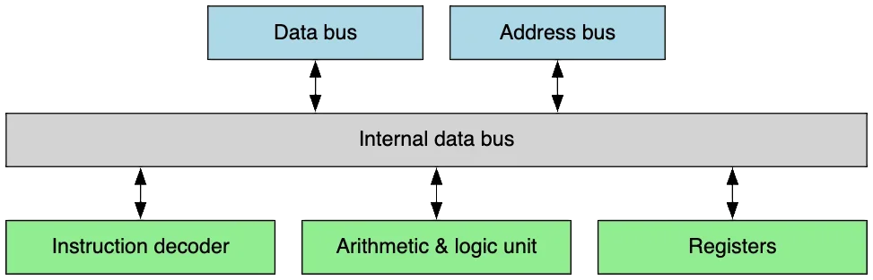
R8 block diagram
Comparisons
The R8’s closest architectural relatives are the Zilog Z80 and MOS 6502. Like the Z80, the R8 is a pointer-flavoured machine that likes to use its 16-bit registers to address memory. Unlike the Z80, though, the R8 has a more regular instruction set. For example, where the Z80 can only address a memory operand through the HL register, the R8 can use any register pair for this purpose.
Like the 6502, the R8 has a minimalist instruction set, making it easy to implement either in hardware or in software. Unlike the 6502, though, the R8 has much more register space (8 bytes compared to 3), eliminating the need for a zero-page addressing mode.
Technical information
The definitive technical documentation for the R8 architecture and instruction set is the R8 Programmer’s Manual (coming soon).
The opcode table is as follows:
| -0 | -1 | -2 | -3 | -4 | -5 | -6 | -7 | -8 | -9 | -A | -B | -C | -D | -E | -F | |
|---|---|---|---|---|---|---|---|---|---|---|---|---|---|---|---|---|
| 0- | halt | nop | sec | clc | sei | cli | ret | rti | ||||||||
| 1- | ld a, N | ld b, N | ld c, N | ld d, N | ld e, N | ld f, N | ld g, N | ld h, N | ld ab, NN | ld cd, NN | ld ef, NN | ld gh, NN | ld sp, NN | ld R, (RR) | ld R1, R2 | ld R, (RR+N) |
| 2- | ld NN, a | ld NN, b | ld NN, c | ld NN, d | ld NN, e | ld NN, f | ld NN, g | ld NN, h | ld (RR), R | ld (RR), N | ld (RR+N), R | |||||
| 3- | inc a | inc b | inc c | inc d | inc e | inc f | inc g | inc h | inc ab | inc cd | inc ef | inc gh | inc sp | inc (RR) | inc (NN) | |
| 4- | dec a | dec b | dec c | dec d | dec e | dec f | dec g | dec h | dec ab | dec cd | dec ef | dec gh | dec sp | dec (RR) | dec (NN) | |
| 5- | add a, N | add b, N | add c, N | add d, N | add e, N | add f, N | add g, N | add h, N | add ab, N | add cd, N | add ef, N | add gh, N | add sp, N | add R1, R2 | ||
| 6- | sub a, N | sub b, N | sub c, N | sub d, N | sub e, N | sub f, N | sub g, N | sub h, N | sub ab, N | sub cd, N | sub ef, N | sub gh, N | sub sp, N | sub R1, R2 | ||
| 7- | cmp a, N | cmp b, N | cmp c, N | cmp d, N | cmp e, N | cmp f, N | cmp g, N | cmp h, N | cmp ab, N | cmp cd, N | cmp ef, N | cmp gh, N | cmp sp, N | cmp R1, R2 | ||
| 8- | and a, N | and b, N | and c, N | and d, N | and e, N | and f, N | and g, N | and h, N | and ab, N | and cd, N | and ef, N | and gh, N | and sp, N | and R1, R2 | ||
| 9- | test a, N | test b, N | test c, N | test d, N | test e, N | test f, N | test g, N | test h, N | test ab, N | test cd, N | test ef, N | test gh, N | test sp, N | test R1, R2 | ||
| A- | or a, N | or b, N | or c, N | or d, N | or e, N | or f, N | or g, N | or h, N | or ab, N | or cd, N | or ef, N | or gh, N | or sp, N | or R1, R2 | ||
| B- | xor a, N | xor b, N | xor c, N | xor d, N | xor e, N | xor f, N | xor g, N | xor h, N | xor ab, N | xor cd, N | xor ef, N | xor gh, N | xor sp, N | xor R1, R2 | ||
| C- | shl R, S | shl R1, R2 | lsr R, S | lsr R1, R2 | asr R, S | asr R1, R2 | ||||||||||
| D- | push a | push b | push c | push d | push e | push f | push g | push h | push ab | push cd | push ef | push gh | push ps | |||
| E- | pop a | pop b | pop c | pop d | pop e | pop f | pop g | pop h | pop ab | pop cd | pop ef | pop gh | pop ps | |||
| F- | bra D | beq D | bne D | bcs D | bcc D | bmi D | bpl D | jmp NN | call NN | trap T |
Flags
The processor status register PS has the following flags:

Status register bits
- Bit 0: Carry (
C) — After addition, this is the carry result. After subtraction or comparison, this flag is set if no borrow occurred (that is, for X - Y, if X >= Y). Increment and decrement instructions do not affect the carry flag. - Bit 1: Zero (
Z) — After instructions with a value result, this flag is set if the result is zero, or cleared otherwise. - Bit 2: Interrupt disable (
I) — When this flag is set, hardware interrupts will be masked (manualtrapinstructions with trap codes in the interrupt range are not affected by this flag). - Bits 3-5 are unused and reserved.
- Bit 6: Overflow (
V) — This flag indicates overflow with signed binary arithmetics. When both operands are of the same sign (i.e. both have either a 0 or a 1 in the sign position at bit 7), but the result is of the opposite sign, the overflow flag is set, indicating that the result is out of range. - Bit 7: Negative (
N) — After instructions with a value result, this flag is set if the sign bit (bit 7) is set.
State diagram
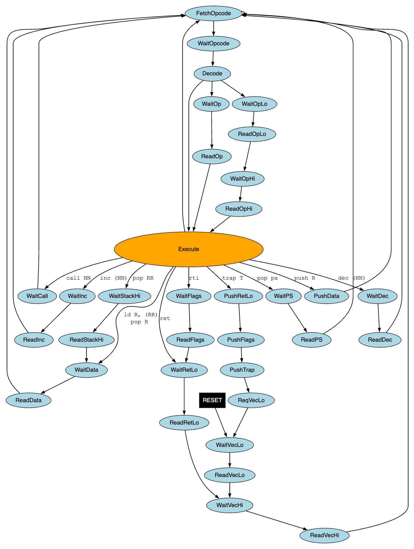
R8 state transitions
History
First manufactured in an alternate 1976 by Solid State Technologies, Inc (SSTi) of Sunnyvale, California, the R8 was a modest commercial success, and was used in a number of sectors including early microcomputers, industrial control, and aerospace. It proved expensive to manufacture, however, and with chip prices falling rapidly, SSTi soon abandoned the CPU market and focused instead on ASICs and dedicated control circuits for industrial applications.
Tutorials
A guided introduction to building a high-level R8 emulator can be found here:
Emulators
There are a number of implementations of the R8 in various languages:
- RX82 — a low-level emulator for a retro computer system based on the R8 (Rust)
- gr8 - a high-level R8 emulator (Go)
- go-r8 — a high-level R8 emulator by Jeremy Grecu (Go)
- ts-r8-emulator — a high-level R8 emulator by Sebastián Alvarez
Libraries
Software packages of interest to R8 emulator developers:
- r8cpu — core types for R8 emulators, such as registers, flags, and instruction kinds (Rust)
Tools
Utilities for those writing R8 programs or implementations.
- r8asm — an assembler / disassembler for R8
Testing and validation
Test programs and suites for validating R8 emulators.
- R8 functional tests — a set of individual instruction and function tests, available as binaries and as assembly-language source code
Books
Books and other published resources on R8:
- Welcome to the Machine (coming soon) — a complete guide to building an R8 emulator, with example code in both Go and Rust